Appendices
Appendix A: Support Content
This appendix provides generic information about the classes and material that are used in this reference documentation.
Classes Used in This Document
The following listings show the classes used throughout this reference guide:
public enum States {
    SI,S1,S2,S3,S4,SF
}
public enum States2 {
	S1,S2,S3,S4,S5,SF,
	S2I,S21,S22,S2F,
	S3I,S31,S32,S3F
}
public enum States3 {
    S1,S2,SH,
    S2I,S21,S22,S2F
}
public enum Events {
    E1,E2,E3,E4,EF
}
Appendix B: State Machine Concepts
This appendix provides generial information about state machines.
Quick Example
Assuming we have states named STATE1 and STATE2 and events named EVENT1 and
EVENT2, you can define the logic of the state machine as the following image shows:
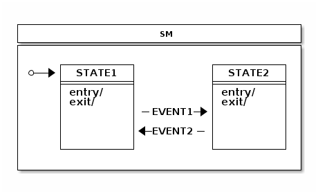
The following listings define the state machine in the preceding image:
public enum States {
	STATE1, STATE2
}

public enum Events {
	EVENT1, EVENT2
}
@Configuration
@EnableStateMachine
public class Config1 extends EnumStateMachineConfigurerAdapter<States, Events> {

	@Override
	public void configure(StateMachineStateConfigurer<States, Events> states)
			throws Exception {
		states
			.withStates()
				.initial(States.STATE1)
				.states(EnumSet.allOf(States.class));
	}

	@Override
	public void configure(StateMachineTransitionConfigurer<States, Events> transitions)
			throws Exception {
		transitions
			.withExternal()
				.source(States.STATE1).target(States.STATE2)
				.event(Events.EVENT1)
				.and()
			.withExternal()
				.source(States.STATE2).target(States.STATE1)
				.event(Events.EVENT2);
	}
}
@WithStateMachine
public class MyBean {

	@OnTransition(target = "STATE1")
	void toState1() {
	}

	@OnTransition(target = "STATE2")
	void toState2() {
	}
}
public class MyApp {

	@Autowired
	StateMachine<States, Events> stateMachine;

	void doSignals() {
		stateMachine
			.sendEvent(Mono.just(MessageBuilder
				.withPayload(Events.EVENT1).build()))
			.subscribe();
		stateMachine
			.sendEvent(Mono.just(MessageBuilder
				.withPayload(Events.EVENT2).build()))
			.subscribe();
	}
}
Glossary
- State Machine
-
The main entity that drives a collection of states, together with regions, transitions, and events.
- State
-
A state models a situation during which some invariant condition holds. The state is the main entity of a state machine where state changes are driven by events.
- Extended State
-
An extended state is a special set of variables kept in a state machine to reduce the number of needed states.
- Transition
-
A transition is a relationship between a source state and a target state. It may be part of a compound transition, which takes the state machine from one state configuration to another, representing the complete response of the state machine to an occurrence of an event of a particular type.
- Event
-
An entity that is sent to a state machine and then drives a various state changes.
- Initial State
-
A special state in which the state machine starts. The initial state is always bound to a particular state machine or a region. A state machine with multiple regions may have a multiple initial states.
- End State
-
(Also called as a final state.) A special kind of state signifying that the enclosing region is completed. If the enclosing region is directly contained in a state machine and all other regions in the state machine are also completed, the entire state machine is completed.
- History State
-
A pseudo state that lets a state machine remember its last active state. Two types of history state exists: shallow (which remembers only top level state) and deep (which remembers active states in sub-machines).
- Choice State
-
A pseudo state that allows for making a transition choice based on (for example) event headers or extended state variables.
- Junction State
-
A pseudo state that is relatively similar to choice state but allows multiple incoming transitions, while choice allows only one incoming transition.
- Fork State
-
A pseudo state that gives controlled entry into a region.
- Join State
-
A pseudo state that gives controlled exit from a region.
- Entry Point
-
A pseudo state that allows controlled entry into a submachine.
- Exit Point
-
A pseudo state that allows controlled exit from a submachine.
- Region
-
A region is an orthogonal part of either a composite state or a state machine. It contains states and transitions.
- Guard
-
A boolean expression evaluated dynamically based on the value of extended state variables and event parameters. Guard conditions affect the behavior of a state machine by enabling actions or transitions only when they evaluate to
TRUEand disabling them when they evaluate toFALSE. - Action
-
A action is a behavior run during the triggering of the transition.
A State Machine Crash Course
This appendix provides a generic crash course to state machine concepts.
States
A state is a model in which a state machine can be. It is always easier to describe state as a real world example rather than trying to use abstract concepts ingeneric documentation. To that end, consider a simple example of a keyboard — most of us use one every single day. If you have a full keyboard that has normal keys on the left side and the numeric keypad on the right side, you may have noticed that the numeric keypad may be in a two different states, depending on whether numlock is activated. If it is not active, pressing the number pad keys result in navigation by using arrows and so on. If the number pad is active, pressing those keys results in numbers being typed. Essentially, the number pad part of a keyboard can be in two different states.
To relate state concept to programming, it means that instead of using flags, nested if/else/break clauses, or other impractical (and sometimes tortuous) logic, you can rely on state, state variables, or another interaction with a state machine.
Pseudo States
Pseudostate is a special type of state that usually introduces more higher-level logic into a state machine by either giving a state a special meaning (such as initial state). A state machine can then internally react to these states by doing various actions that are available in UML state machine concepts.
Initial
The Initial pseudostate state is always needed for every single state machine, whether you have a simple one-level state machine or a more complex state machine composed of submachines or regions. The initial state defines where a state machine should go when it starts. Without it, a state machine is ill-formed.
End
The Terminate pseudostate (which is also called “end state”) indicates that a particular state machine has reached its final state. Effectively, this mean that a state machine no longer processes any events and does not transit to any other state. However, in the case where submachines are regions, a state machine can restart from its terminal state.
Choice
You can use the Choice pseudostate choose a dynamic conditional branch of a transition from this state. The dynamic condition is evaluated by guards so that one branch is selected. Usually a simple if/elseif/else structure is used to make sure that one branch is selected. Otherwise, the state machine might end up in a deadlock, and the configuration is ill-formed.
Junction
The Junction pseudostate is functionally similar to choice, as both are implemented with if/elseif/else structures. The only real difference is that junction allows multiple incoming transitions, while choice allows only one. Thus difference is largely academic but does have some differences, such as when a state machine is designed is used with a real UI modeling framework.
History
You can use the History pseudostate to remember the last active state
configuration. After a state machine has exited, you can use a history state
to restore a previously known configuration. There are two types
of history states available: SHALLOW (which remembers only the active state of a
state machine itself) and DEEP (which also remembers nested states).
A history state could be implemented externally by listening state machine events, but this would soon make for very difficult logic, especially if a state machine contains complex nested structures. Letting the state machine itself handle the recording of history states makes things much simpler. The user need only create a transition into a history state, and the state machine handles the needed logic to go back to its last known recorded state.
In cases where a Transition terminates on a history state when the state has not been previously entered (in other words, no prior history exists) or it had reached its end state, a transition can force the state machine to a specific substate, by using the default history mechanism. This transition originates in the history state and terminates on a specific vertex (the default history state) of the region that contains the history state. This transition is taken only if its execution leads to the history state and the state had never before been active. Otherwise, the normal history entry into the region is executed. If no default history transition is defined, the standard default entry of the region is performed.
Fork
You can use the Fork pseudostate to do an explicit entry into one or more regions. The following image shows how a fork works:

The target state can be a parent state that hosts regions, which simply means that regions are activated by entering their initial states. You can also add targets directly to any state in a region, which allows more controlled entry into a state.
Join
The Join pseudostate merges together several transitions that originate from different regions. It is generally used to wait and block for participating regions to get into its join target states. The following image shows how a join works:

The source state can be a parent state that hosts regions, which means that join states are the terminal states of the participating regions. You can also define source states to be any state in a region, which allows controlled exit from regions.
Entry Point
An Entry Point pseudostate represents an entry point for a state machine or a composite state that provides encapsulation of the insides of the state or state machine. In each region of the state machine or composite state that owns the entry point, there is at most a single transition from the entry point to a vertex within that region.
Exit Point
An Exit Point pseudostate is an exit point of a state machine or composite state that provides encapsulation of the insides of the state or state machine. Transitions that terminate on an exit point within any region of the composite state (or a state machine referenced by a submachine state) imply exiting of this composite state or submachine state (with execution of its associated exit behavior).
Guard Conditions
Guard conditions are expressions which evaluates to either TRUE or
FALSE, based on extended state variables and event parameters. Guards
are used with actions and transitions to dynamically choose whether a
particular action or transition should be run. The various spects of guards,
event parameters, and extended state variables exist to make state
machine design much more simple.
Events
Event is the most-used trigger behavior to drive a state machine. There are other ways to trigger behavior in a state machine (such as a timer), but events are the ones that really let users interact with a state machine. Events are also called “signals”. They basically indicate something that can possibly alter a state machine state.
Transitions
A transition is a relationship between a source state and a target state. A switch from one state to another is a state transition caused by a trigger.
Internal Transition
Internal transition is used when an action needs to be run without causing a state transition. In an internal transition, the source state and the target state is always the same, and it is identical with a self-transition in the absence of state entry and exit actions.
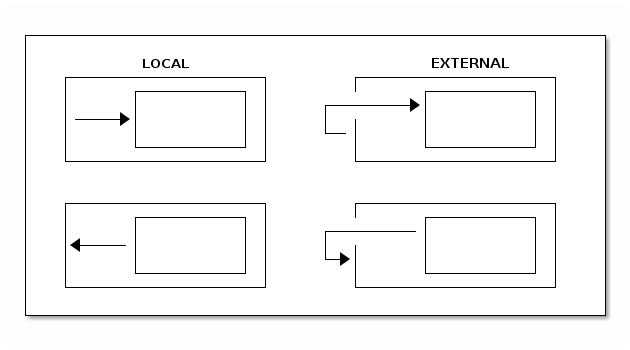
External versus Local Transitions
In most cases, external and local transitions are functionally equivalent, except in cases where the transition happens between super and sub states. Local transitions do not cause exit and entry to a source state if the target state is a substate of a source state. Conversely, local transitions do not cause exit and entry to a target state if the target is a superstate of a source state. The following image shows the difference between local and external transitions with very simplistic super and sub states:
Actions
Actions really glue state machine state changes to a user’s own code. A state machine can run an action on various changes and on the steps in a state machine (such as entering or exiting a state) or doing a state transition.
Actions usually have access to a state context, which gives running code a choice to interact with a state machine in various ways. State context exposes a whole state machine so that a user can access extended state variables, event headers (if a transition is based on an event), or an actual transition (where it is possible to see more detailed about where this state change is coming from and where it is going).
Hierarchical State Machines
The concept of a hierarchical state machine is used to simplify state design when particular states must exist together.
Hierarchical states are really an innovation in UML state machines over
traditional state machines, such as Mealy or Moore machines.
Hierarchical states lets you define some level of abstraction (parallel
to how a Java developer might define a class structure with abstract
classes). For example, with a nested state machine, you can
define transition on a multiple level of states (possibly with
different conditions). A state machine always tries to see if the current
state is able to handle an event, together with transition guard
conditions. If these conditions do not evaluate to TRUE, the state
machine merely see what the super state can handle.
Regions
Regions (which are also called as orthogonal regions) are usually viewed as exclusive OR (XOR) operations applied to states. The concept of a region in terms of a state machine is usually a little difficult to understand, but things gets a little simpler with a simple example.
Some of us have a full size keyboard with the main keys on the left side and numeric keys on the right side. You have probably noticed that both sides really have their own state, which you see if you press a “numlock” key (which alters only the behaviour of the number pad itself). If you do not have a full-size keyboard, you can buy an external USB number pad. Given that the left and right side of a keyboard can each exist without the other, they must have totally different states, which means they are operating on different state machines. In state machine terms, the main part of a keyboard is one region and the number pad is another region.
It would be a little inconvenient to handle two different state machines as totally separate entities, because they still work together in some fashion. This independence lets orthogonal regions combine together in multiple simultaneous states within a single state in a state machine.
Appendix C: Distributed State Machine Technical Paper
This appendix provides more detailed technical documentation about using a Zookeeper instance with Spring Statemachine.
Abstract
Introducing a “distributed state” on top of a single state machine
instance running on a single JVM is a difficult and a complex topic.
The concept of a “Distributed State Machine” introduces a few relatively complex
problems on top of a simple state machine, due to its run-to-completion
model and, more generally, because of its single-thread execution model,
though orthogonal regions can be run in parallel. One other natural
problem is that state machine transition execution is driven by triggers,
which are either event or timer based.
Spring State Machine tries to solve the problem of spanning a generic “State Machine” through a JVM boundary by supporting distributed state machines. Here we show that you can use generic “State Machine” concepts across multiple JVMs and Spring Application Contexts.
We found that, if Distributed State Machine abstraction is carefully chosen
and backing distributed state repository guarantees CP readiness, it is
possible to create a consistent state machine that can share
distributed state among other state machines in an ensemble.
Our results demonstrate that distributed state changes are consistent if the backing repository is “CP” (discussed later). We anticipate our distributed state machine can provide a foundation to applications that need to work with shared distributed states. This model aims to provide good methods for cloud applications to have much easier ways to communicate with each other without having to explicitly build these distributed state concepts.
Introduction
Spring State Machine is not forced to use a single threaded execution model, because, once multiple regions are used, regions can be executed in parallel if the necessary configuration is applied. This is an important topic, because, once a user wants to have parallel state machine execution, it makes state changes faster for independent regions.
When state changes are no longer driven by a trigger in a local JVM or a local state machine instance, transition logic needs to be controlled externally in an arbitrary persistent storage. This storage needs to have a way to notify participating state machines when distributed state is changed.
CAP Theorem states that it is impossible for a distributed computer system to simultaneously provide all three of the following guarantees: consistency, availability, and partition tolerance.
This means that, whatever is chosen for a backing persistence storage, it is advisable to be “CP”. In this context, “CP” means “consistency” and “partition tolerance”. Naturally, a distributed Spring Statemachine does not care about its “CAP” level but, in reality, “consistency” and “partition tolerance” are more important than “availability”. This is an exact reason why (for example) Zookeeper uses “CP” storage.
All tests presented in this article are accomplished by running custom Jepsen tests in the following environment:
-
A cluster having nodes n1, n2, n3, n4 and n5.
-
Each node has a
Zookeeperinstance that constructs an ensemble with all other nodes. -
Each node has a Web sample installed, to connect to a local
Zookeepernode. -
Every state machine instance communicates only with a local
Zookeeperinstance. While connecting a machine to multiple instances is possible, it is not used here. -
All state machine instances, when started, create a
StateMachineEnsembleby using a Zookeeper ensemble. -
Each sample contains a custom rest API, which Jepsen uses to send events and check particular state machine statuses.
All Jepsen tests for Spring Distributed Statemachine are available from
Jepsen
Tests.
Generic Concepts
One design decision of a Distributed State Machine was not to make each
individual state machine instance be aware that it is part of a
“distributed ensemble”. Because the main functions and features of a
StateMachine can be accessed through its interface, it makes sense to
wrap this instance in a DistributedStateMachine, which
intercepts all state machine communication and collaborates with an
ensemble to orchestrate distributed state changes.
One other important concept is to be able to persist enough
information from a state machine to reset a state machine state
from an arbitrary state into a new deserialized state. This is naturally
needed when a new state machine instance joins with an ensemble
and needs to synchronize its own internal state with a distributed
state. Together with using concepts of distributed states and state
persisting, it is possible to create a distributed state machine.
Currently, the only backing repository of a Distributed State Machine is
implemented by using Zookeeper.
As mentioned in Using Distributed States, distributed states are enabled by
wrapping an instance of a StateMachine in a
DistributedStateMachine. The specific StateMachineEnsemble
implementation is ZookeeperStateMachineEnsemble provides
integration with Zookeeper.
The Role of ZookeeperStateMachinePersist
We wanted to have a generic interface (StateMachinePersist) that
Can persist StateMachineContext into arbitrary storage and
ZookeeperStateMachinePersist implements this interface for
Zookeeper.
The Role of ZookeeperStateMachineEnsemble
While a distributed state machine uses one set of serialized
contexts to update its own state, with zookeeper, we have a
conceptual problem around how to listen to these context changes. We
can serialize context into a zookeeper znode and eventually
listen when the znode data is modified. However, Zookeeper does not
guarantee that you get a notification for every data change,
because a registered watcher for a znode is disabled once it fires
and the user need to re-register that watcher. During this short time,
a znode data can be changed, thus resulting in missing events. It is
actually very easy to miss these events by changing data from
multiple threads in a concurrent manner.
To overcome this issue, we keep individual context changes
in multiple znodes and we use a simple integer counter to mark
which znode is the current active one. Doing so lets us replay missed
events. We do not want to create more and more znodes and then later
delete old ones. Instead, we use the simple concept of a circular
set of znodes. This lets us use a predefined set of znodes where
the current node can be determined with a simple integer counter. We already have
this counter by tracking the main znode data version (which, in
Zookeeper, is an integer).
The size of a circular buffer is mandated to be a power of two, to avoid trouble when the integer goes to overflow. For this reason, we need not handle any specific cases.
Distributed Tolerance
To show how a various distributed actions against a state machine work in real life, we use a set of Jepsen tests to simulate various conditions that might happen in a real distributed cluster. These include a “brain split” on a network level, parallel events with multiple “distributed state machines”, and changes in “extended state variables”. Jepsen tests are based on a sample Web, where this sample instance runs on multiple hosts together with a Zookeeper instance on every node where the state machine is run. Essentially, every state machine sample connects to a local Zookeeper instance, which lets us, by using Jepsen, to simulate network conditions.
The plotted graphs shown later in this chapter contain states and events that directly map to a state chart, which you can be find in Web.
Isolated Events
Sending an isolated single event into exactly one state machine in an ensemble is the simplest testing scenario and demonstrates that a state change in one state machine is properly propagated into other state machines in an ensemble.
In this test, we demonstrate that a state change in one machine eventually causes a consistent state change in other machines. The following image shows the events and state changes for a test state machine:
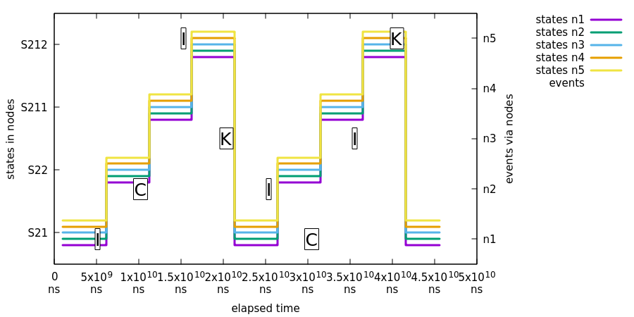
In the preceding image:
-
All machines report state
S21. -
Event
Iis sent to noden1and all nodes report state change fromS21toS22. -
Event
Cis sent to noden2and all nodes report state change fromS22toS211. -
Event
Iis sent to noden5and all nodes report state change fromS211toS212. -
Event
Kis sent to noden3and all nodes report state change fromS212toS21. -
We cycle events
I,C,I, andKone more time, through random nodes.
Parallel Events
One logical problem with multiple distributed state machines is that, if the same event is sent into multiple state machines at exactly the same time, only one of those events causes a distributed state transitions. This is a somewhat expected scenario, because the first state machine (for this event) that is able to change a distributed state controls the distributed transition logic. Effectively, all other machines that receive this same event silently discard the event, because the distributed state is no longer in a state where a particular event can be processed.
In the test shown in the following image, we demonstrate that a state change caused by a parallel event throughout an ensemble eventually causes a consistent state change in all machines:
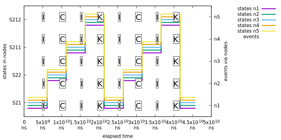
In the preceding image, we use the same event flow that we used in the previous sample (Isolated Events), with the difference that events are always sent to all nodes.
Concurrent Extended State Variable Changes
Extended state machine variables are not guaranteed to be atomic at any given time, but, after a distributed state change, all state machines in an ensemble should have a synchronized extended state.
In this test, we demonstrate that a change in extended state variables in one distributed state machine eventually becomes consistent in all the distributed state machines. The following image shows this test:
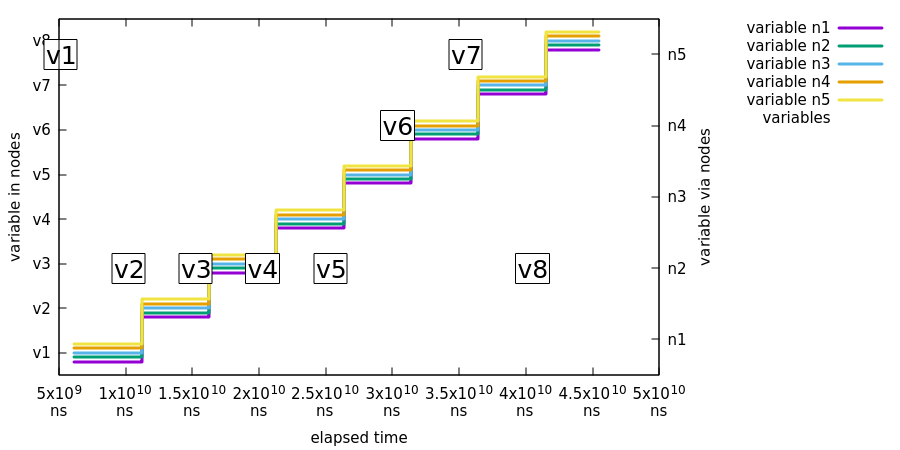
In the preceding image:
-
Event
Jis send to noden5with event variabletestVariablehaving valuev1. All nodes then report having a variable namedtestVariablewith a value ofv1. -
Event
Jis repeated from variablev2tov8, doing the same checks.
Partition Tolerance
We need to always assume that, sooner or later, things in a cluster go bad, whether it is a crash of a Zookeeper instance, a state machine crash, or a network problem such as a “brain split”. (A brain split is a situation where existing cluster members are isolated so that only parts of hosts are able to see each other). The usual scenario is that a brain split creates minority and majority partitions of an ensemble such that hosts in the minority cannot participate in an ensemble until the network status has been healed.
In the following tests, we demonstrate that various types of brain split in an ensemble eventually cause a fully synchronized state of all the distributed state machines.
There are two scenarios that have a straight brain split in a
network where where Zookeeper and Statemachine instances are
split in half (assuming each Statemachine connects to a
local Zookeeper instance):
-
If the current zookeeper leader is kept in a majority, all clients connected to the majority keep functioning properly.
-
If the current zookeeper leader is left in the minority, all clients disconnect from it and try to connect back till previous minority members have successfully joined back to existing majority ensemble.
| In our current Jepsen tests, we cannot separate Zookeeper split-brain scenarios between the leader being left in the majority or in the minority, so we need to run the tests multiple times to accomplish this situation. |
In the following plots, we have mapped a state machine error state into an
error to indicate that the state machine is in an error state instead of
a normal state. Please remember this when interpreting chart states.
|
In this first test, we show that, when an existing Zookeeper leader was kept in the majority, three out of five machines continue as is. The following image shows this test:
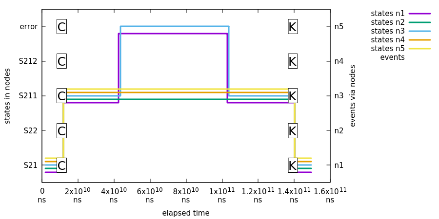
In the preceding image:
-
The first event,
C, is sent to all machines, leading a state change toS211. -
Jepsen nemesis causes a brain split, which causes partitions of
n1/n2/n5andn3/n4. Nodesn3/n4are left in the minority, and nodesn1/n2/n5construct a new healthy majority. Nodes in the majority keep functioning without problems, but nodes in the minority go into error states. -
Jepsen heals the network and, after some time, nodes
n3/n4join back into the ensemble and synchronize its distributed status. -
Finally, event
K1is sent to all state machines to ensure that the ensemble is working properly. This state change leads back to stateS21.
In the second test, we show that, when the existing zookeeper leader was kept in the minority, all machines error out. The following image shows the second test:
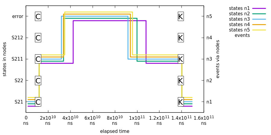
In the preceding image:
-
The first event,
C, is sent to all machines leading to a state change toS211. -
Jepsen nemesis causes a brain split, which causes partitions such that the existing
Zookeeperleader is kept in the minority and all instances are disconnected from the ensemble. -
Jepsen heals the network and, after some time, all nodes join back into the ensemble and synchronize its distributed status.
-
Finally, event
K1is sent to all state machines to ensure that ensemble workS properly. This state change leads back to stateS21.
Crash and Join Tolerance
In this test, we demonstrate that killing an existing state machine and then joining a new instance back into an ensemble keeps the distributed state healthy and the newly joined state machines synchronize their states properly. The following image shows the crash and join tolerance test:
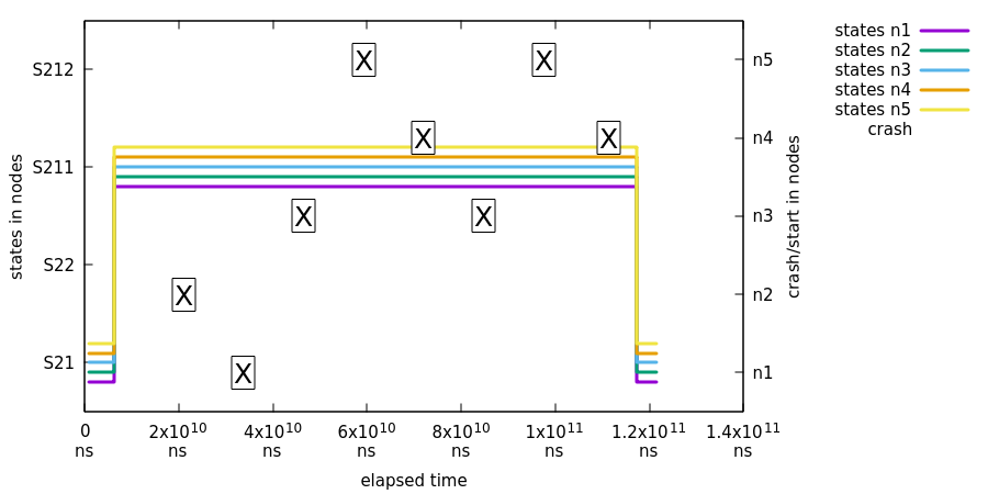
In this test, states are not checked between first the X and last the X.
Thus, the graph shows a flat line in between. The states are checked
exactly where the state change happens between S21 and S211.
|
In the preceding image:
-
All state machines are transitioned from the initial state (
S21) into stateS211so that we can test proper state synchronize during the join. -
Xmarks when a specific node has been crashed and started. -
At the same time, we request states from all machines and plot the result.
-
Finally, we do a simple transition back to
S21fromS211to make sure that all state machines still function properly.
Developer Documentation
This appendix provides generic information for adevelopers who may want to contribute or other people who want to understand how state machine works or understand its internal concepts.
StateMachine Config Model
StateMachineModel and other related SPI classes are an abstraction
between various configuration and factory classes. This also allows
easier integration for others to build state machines.
As the following listing shows, you can instantiate a state machine by building a model with configuration data classes and then asking a factory to build a state machine:
// setup configuration data
ConfigurationData<String, String> configurationData = new ConfigurationData<>();

// setup states data
Collection<StateData<String, String>> stateData = new ArrayList<>();
stateData.add(new StateData<String, String>("S1", true));
stateData.add(new StateData<String, String>("S2"));
StatesData<String, String> statesData = new StatesData<>(stateData);

// setup transitions data
Collection<TransitionData<String, String>> transitionData = new ArrayList<>();
transitionData.add(new TransitionData<String, String>("S1", "S2", "E1"));
TransitionsData<String, String> transitionsData = new TransitionsData<>(transitionData);

// setup model
StateMachineModel<String, String> stateMachineModel = new DefaultStateMachineModel<>(configurationData, statesData,
		transitionsData);

// instantiate machine via factory
ObjectStateMachineFactory<String, String> factory = new ObjectStateMachineFactory<>(stateMachineModel);
StateMachine<String, String> stateMachine = factory.getStateMachine();